SPEAD Channelised Data Test
Purpose
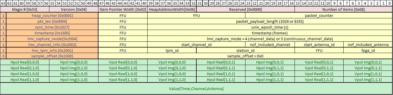
This test verifies the SPEAD header fields of the channelised data coming from the LMC module in the firmware. Channelised data can be requested in three modes, burst (a.k.a. frequency sweep), single channel (a.k.a. continuous) and integrated. The SPEAD packets are captured using the DAQ receiver. This test uses the SPEAD header metadata passed by the DAQ for verifcation. Given below is the SPEAD header specification which is verified in this test.
When requesting burst mode data, each FPGA is given a “numer of samples” value that determines the number of samples per frequency channel the FPGA should transmit. For packets transmitted from the UDP core in the FPGAs (as in this test), each SPEAD packet holds 256 samples. In this test, the burst mode request is configured for 512 samples for all frequency channels (0-511) meaning 2 packets per frequency channel, per FPGA; yielding 2048 packets per TPM. The FPGAs will automatically de-assert the channelised data request to finish the transmission when the requested data has been sent. The resulting 2048 SPEAD packet headers are captured by the DAQ and given to the test via a callback method so that the header contents can be verified.
The continuous channel mode is used to transmit a single frequency channel, continously. Meaning the FPGAs do not de-assert the request automatically but rather wait for an external command to stop the transmission. In the test, this is done as soon as a callback for continuous mode data is received from the DAQ. The channel ID that will be transmitted for this mode can be selected using the single_ch_id configuration of the test. This channel ID is then compared to the start_channel_id field of the SPEAD header.
The integrated channel mode is configured for an integration time, which is 1 second in this test. In this mode the FPGAs continuously integrate the channelised data and transmit 16 packets per FPGA per integration time. The DAQ does a callback every 2 integrations, so the test verfies 32 SPEAD headers per FPGA (64 per tile).
NOTE: This test operates on all TPMs in a station individually (when single_tpm_id=-1). For data acquisition to function correctly, the network interfaces on the TPM must be working, as well as the link to the LMC destination. The LMC destination must be configured to route traffic to the server running the tests. For all tests the simplest option is for the CSP and LMC destinations to be the same network interface, routing all traffic to the server running the tests.
Methodology
Establish connection to the station and specified TPM(s).
Configure and initialise the DAQ receiver with the required UDP port and network interface.
Start the DAQ for all 3 channelised data modes (burst, continuous, integrated).
Set expected values to the SPEAD header fields.
Request chanelised burst mode data from the TPM.
Wait for the DAQ to receive data.
Extract the spead header fields from the data callback.
Verify SPEAD header fields by comparing with the expected values.
Update the expected values as necessary for integrated mode.
Request integrated channelised data from the TPM.
Stop integrated data when the DAQ does a callback, extract the spead header fields as before.
Verify SPEAD header fields by comparing with the expected values.
Update the expected values as necessary for continuous mode.
Request channelised continuous mode data from the TPM.
Stop continuous data when the DAQ does a callback.
Verify SPEAD header fields by comparing with the expected values.
Stop the DAQ when the test verifies all modes for the tile.
Repeat steps 2-17 for other TPMs in the station (if single_tpm_id=-1).
Stop the DAQ and clean up temporary directory.