Tile Beam Tracking Test
Purpose
This test verifies the beam tracking functionality in the tile beamformer firmware.
The tile beamformer is a firmware component that forms beams by summing signals from 16 antennas for a given coarse frequency channel. Beam tracking is achieved by applying a linear delay rate to each antenna within a beam. The maximum configurable delay rate is approximately 17.24 ps/s.
Beam tracking is validated by applying a set of delay rates to selected antennas and comparing the resulting beam values over time against calculated values. Beam data is sampled by requesting the LMC data type “beam data” and capturing it using the DAQ receiver.
Note
This test operates only on the first TPM in a station.
Note
For data acquisition to function correctly:
TPM network interfaces must be operational.
The link to the LMC destination must be active.
The LMC destination must be configured to route traffic to the server running the tests.
For simplicity, the CSP and LMC destinations should use the same network interface, routing all traffic to the test server.
Test Options
This test provides three options selectable via the test_option parameter. Each option determines which antennas contribute to each beam polarisation:
test_option = 0(default):Antennas 0–7 (with negative delay rates) assigned to beam polarisation 0
Antennas 8–15 (with positive delay rates) assigned to beam polarisation 1
test_option = 1:Antenna 0 (with maximum negative delay rate) assigned to beam polarisation 0
Antennas 0–15 (all) assigned to beam polarisation 1
test_option = 2:Antenna 8 (with zero delay rate) assigned to beam polarisation 0
Antennas 1–15 (with zero net delay rate) assigned to beam polarisation 1
Quantisation & Limits of Delay Rates in Firmware
Tracking delay rates in firmware are stored as 12-bit signed integers (programmed_rate), with valid values from -2048 to +2047 units.
To convert the intended delay rate (in seconds per second) into the delay rate programmed in firmware:
programmed_rate = int(round(intended_rate * ((1024.0 * 1080e-9 * 2**37) / 1280e-9)))
To reverse this and get the effective rate used in calculations:
effective_rate = programmed_rate * 1280e-9 / (1024.0 * 1080e-9 * 2**37)
This gives us the range limits of approximately ±17.24 ps/s for the tracking delay rates.
The step width of the quantised delay rate is approximately 8.42 fs/s per unit of programmed_rate.
This means each increment or decrement in the 12-bit signed integer (programmed_rate`) changes the effective delay rate by about 8.42 fs/s.
Note
Always use effective_rate for beam calculations, as quantisation may slightly alter the intended rate.
Calculation of Expected Beam Values
In this test, 16 linear tracking delay rates r are programmed in firmware for the 16 antennas on a TPM:
r = [
    -1.72382931e-11, -1.50835065e-11, -1.29287198e-11, -1.07739332e-11,
    -8.61914655e-12, -6.46435991e-12, -4.30957327e-12, -2.15478664e-12,
     0.00000000e+00,  2.15478664e-12,  4.30957327e-12,  6.46435991e-12,
     8.61914655e-12,  1.07739332e-11,  1.29287198e-11,  1.50835065e-11
]  # units: s/s
The signals from the tests generator for all 16 antennas are identical, having a constant frequency f.
Given that:
A₀ = magnitude of the beam at time t = 0
φ₀ = phase of the beam at time t = 0
rₖ = Tracking delay rate programmed for antenna k
The expected phase φₖ(t) of the tracked beam at time t for channel frequency f for antenna k is given by:
The expected complex beam value B(t) at time t made from all 16 antennas can then be calculated using the formula:
Methodology
Connection is established to the station and the tile with the specified TPM ID.
DAQ receiver is configured and initialised with the required UDP port and network interface.
All JESD (ADC) channels are disabled to get ready to use the internal test generator.
The test starts at the first specified frequency channel. This defaults to channel 0.
The internal tone generator is configured with the centre frequency of the given frequency channel and zero delays.
The calibration coefficient matrices are programmed with a gain of 1.0, such that one set of antennas contributes to beam polarisation 0 and the other set contributes to beam polarisation 1.
The delay and delay rates are initially set to zero in firmware to generate an unpointed reference beam of the selected antennas.
A linear array of 16 delay rates in the range [-max_rate, max_rate) is programmed for the 16 antennas to generate a tracked beam. Here, max_rate ≈ 17.2 ps/s.
The tracked beam is captured by requesting an LMC snapshot of beam data from the TPM and compared with the expected beam roughly every 2.5 seconds.
The beam at time t=0 serves as the reference unpointed beam. Its phase and magnitude are used in calculating expected tracked beam values.
This entire process is repeated (starting again at step 5.) for more coarse frequency channels up to the last specified frequency channel. Default channels used: 0-7.
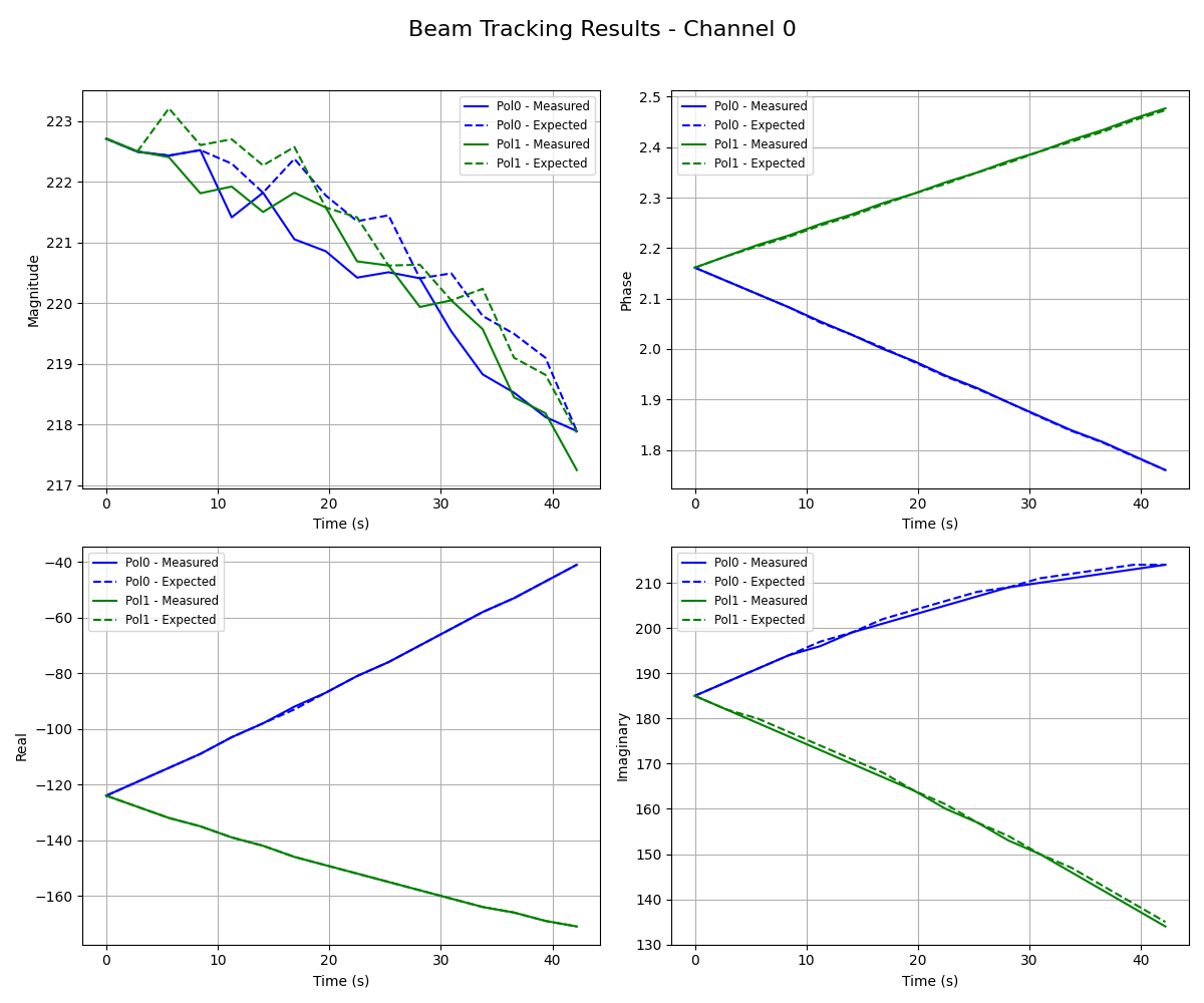
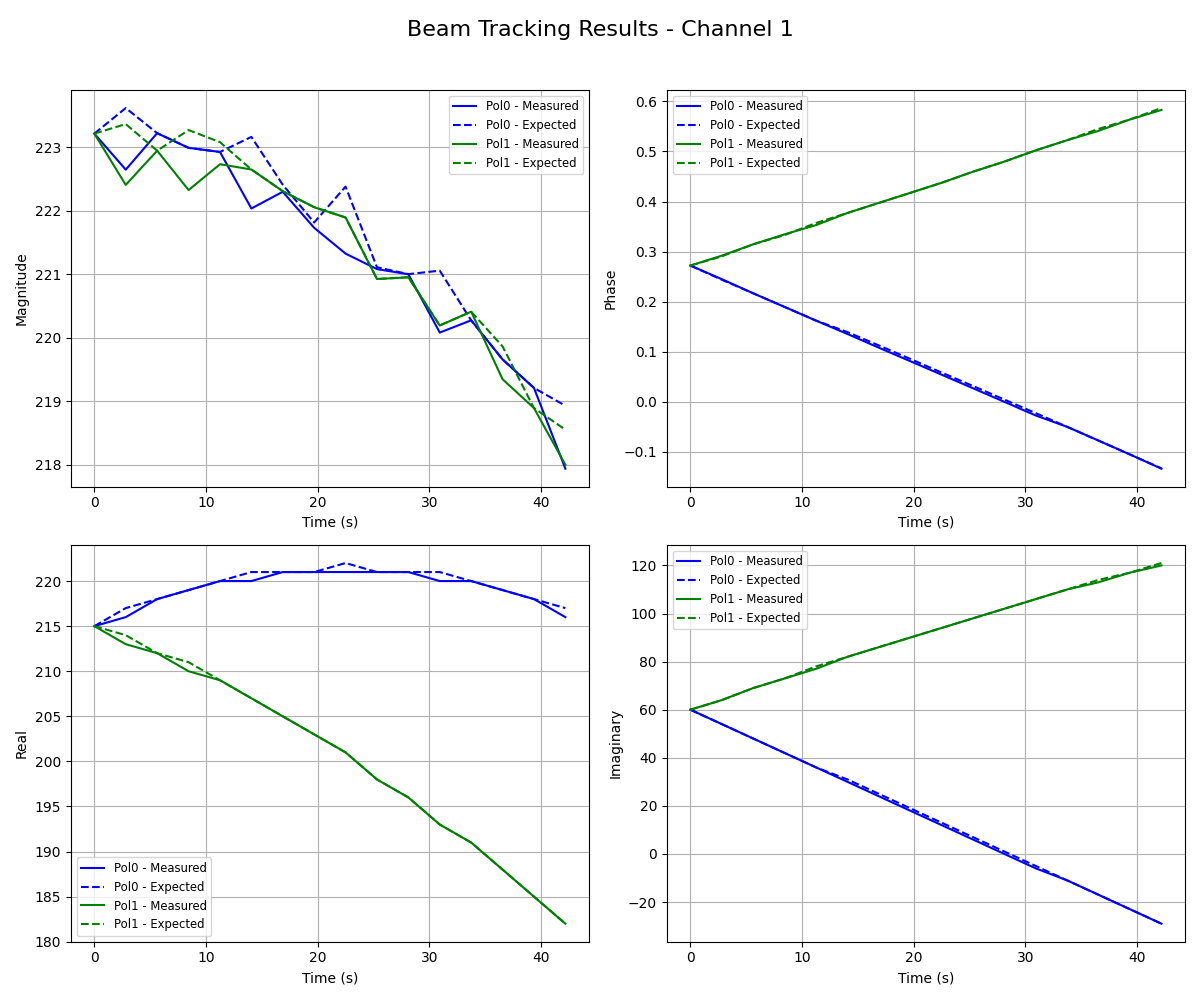
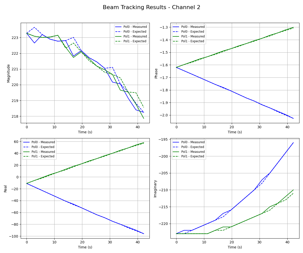
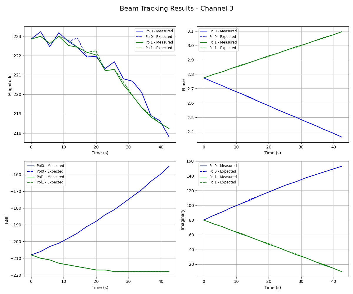
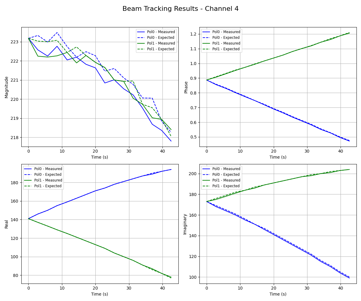
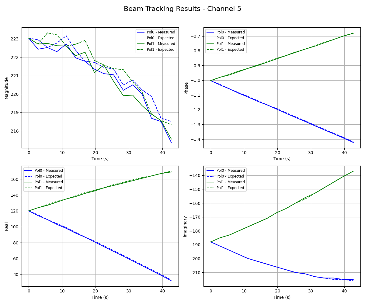
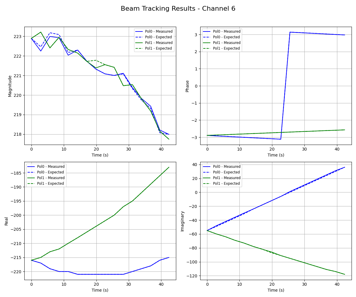
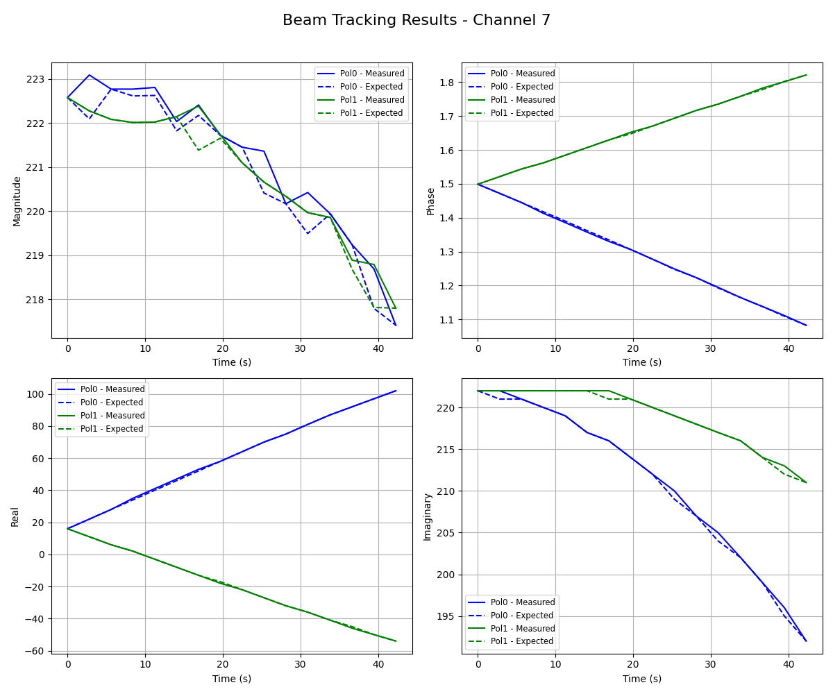
Results
The plots in this section show measured (captured) and expected (calculated) tracked beam values over time corresponding to channels 0–7. Starting frequency is set as 156.25 MHz.
Results for Test Option 0: